RC51 ROAD COMFORT RC-BARS - INSTALLATION GUIDE
Thank you for your purchase of RC-Bars. The higher and
slightly wider positioning will
enable you to take your RC51 on longer rides. They also
have the following
advantages over Heli-Bars for the RC51 that were discontinued years ago:
- Higher strength 4130 Cr-Mo steel construction instead
of mild steel.
- Clamp bushings are TIG welded to sleeves instead of
brazed.
- All TIG Welding done with ER80S-D2 rod used on race car
frames and airplane fuselages.
- Pinch bolts are stainless steel M6 x 1.0 x 25mm instead
of zinc plated steel.
- Satin black powdercoating instead of gloss black.
- Step-by-step detailed installation instructions with
high
resolution pictures.
|
PLEASE READ THIS CAUTION PARAGRAPH - IT IS
IMPORTANT:
I cannot assume liability for injury or
loss of property from your installation or use of RC-Bars. You are responsible
for ensuring that your motorcycle is safe to operate each time before you ride
it. After installation of RC-Bars it is your responsibility to make sure they
are installed properly and safe to ride with. RC-Bars were not designed for
"stunt" riding and any such use is at your own risk. It is extremely
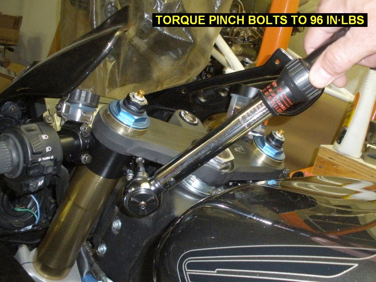
important that you properly torque the pinch bolts to 96 in-lbs.
Over-tightening can possibly result in hardware failure and under-tightening
can possibly result in loose handlebars. Use of Torque-Seal or dabs of paint
on the pinch bolts after installation is a good way to ensure they have not
loosened over time. Otherwise you should periodically check security of the
pinch bolts. Using Loc-Tite is not recommended because a tiny amount of anti-sieze
has been applied to the pinch bolt threads to prevent corrosion. You must
ensure that unrestricted lock-to-lock steering is available without
interference from any cable, hoses, bodywork or the fuel tank. If RC-Bars are
subjected to abnormally high forces such as a tip-over, crash or collision, it
is your responsibility to inspect and determine any damage to them and make a
decision if they are still safe to use. If the bars are bent, have any cracks,
tears or deep gouges in the metal, you should consider them unsafe and not use
them further. If you use the handlebars as a tie-down point keep in mind that
it is possible the bars may rotate on the fork tubes if subjected to
abnormally high forces. Thus it would always be prudent to use secondary
tie-downs on other parts of the motorcycle. Check alignment of the RC-Bars
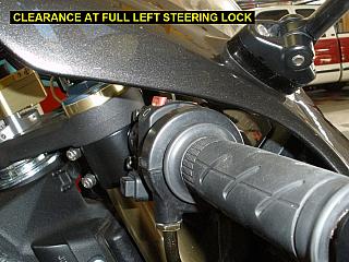
afterwards and reposition them if needed. When you first ride with RC-Bars,
keep in mind that at full lock steering, your inside thumb will not have as
much clearance between the grip and the fuel tank as it did before. To avoid
low speed crashes when doing u-turns or maneuvering in parking lots, you
should anticipate this. Sit on the bike with your normal riding gloves on and
explore the maximum steering limits back and forth with your hands on the bars
until you develop a method of holding the inside bar that allows full lock
steering in both directions. If your bars are positioned correctly, sliding
your inside hand outboard on the grip, or moving your thumb from under the
grip to on top of the grip is usually all that is needed. By practicing in
advance you can hopefully avoid the pain of your thumb acting as the steering
lock. If you disagree with anything in this paragraph, do not install the
RC-Bars and instead return them to me for full refund.
|
RETURN POLICY:
If you install RC-Bars and discover you are dissatisfied after riding with
them, you can return them to me within 30 days, and I will refund your $220, assuming they are only scratched from
installation/use, not damaged otherwise. You pay
for return shipping though. I
specifically know that each set of bars has been inspected thoroughly thru the
manufacturing process and each bar has been fit tested on my personal bike.
Provided they are not damaged during shipment to you, there is zero chance of
you receiving a defective part. If you experience shipping damage contact me
and I'll do a full refund.
INSTALLATION OF RC-BARS
Installation Goal:
- To install RC-Bars securely, ensuring no control cable or
hydraulic hose interference while steering lock to lock and with no damage to
finished surfaces of the motorcycle. Although there are many steps to this
installation, you will discover that each step is really not that difficult
and the whole installation will not take more than a few hours of your time
if you have the tools listed.
- Read through it these instructions once before you
start to get the overall
picture, then follow it step-by-step.
- Note that some installation pictures below are of the
prototype bars, yours of course will be powdercoated black and look much
nicer!
Tools Required :
- Of course you are entitled to use whatever tools and
methods you think work best, listed below is what has worked at least once!
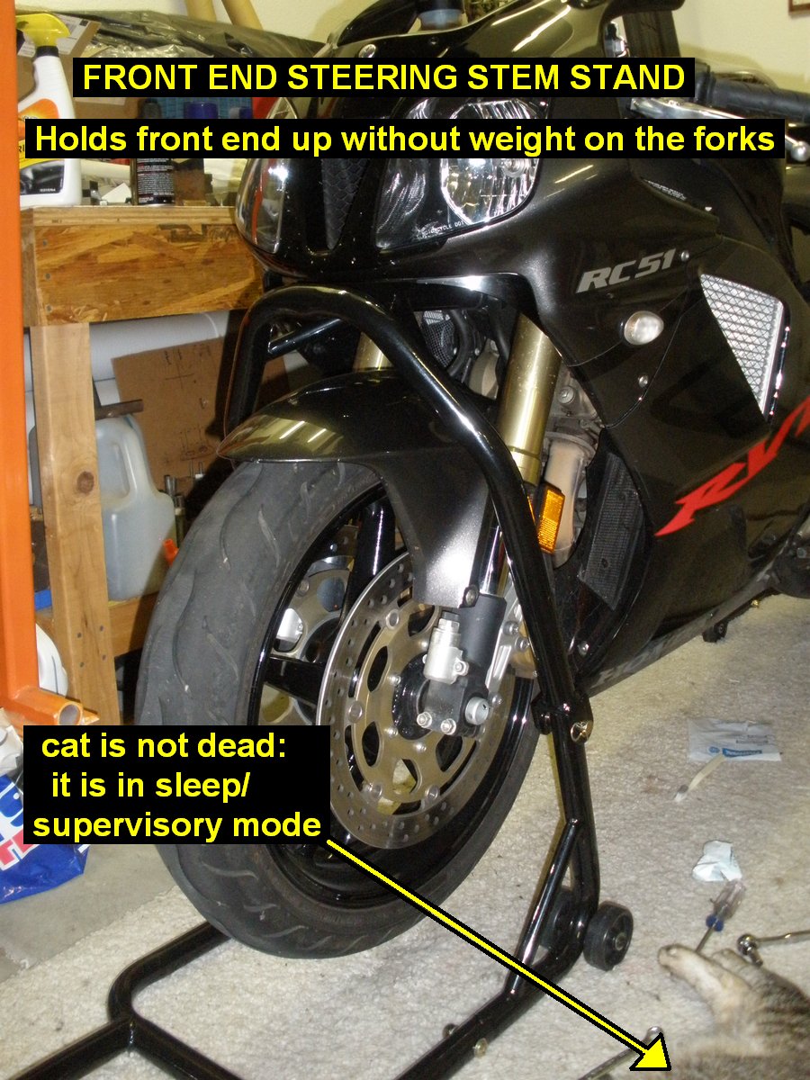
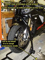
- Motorcycle stands, the best setup is a rear PitBull
type stand and the front end on a steering stem support stand. Otherwise
you'll need to figure out something to
take the weight off the forks since the top triple clamp will be removed.
- Dremel tool, hacksaw blade or other small saw blade to
cut the cast aluminum tab at the front brake line.
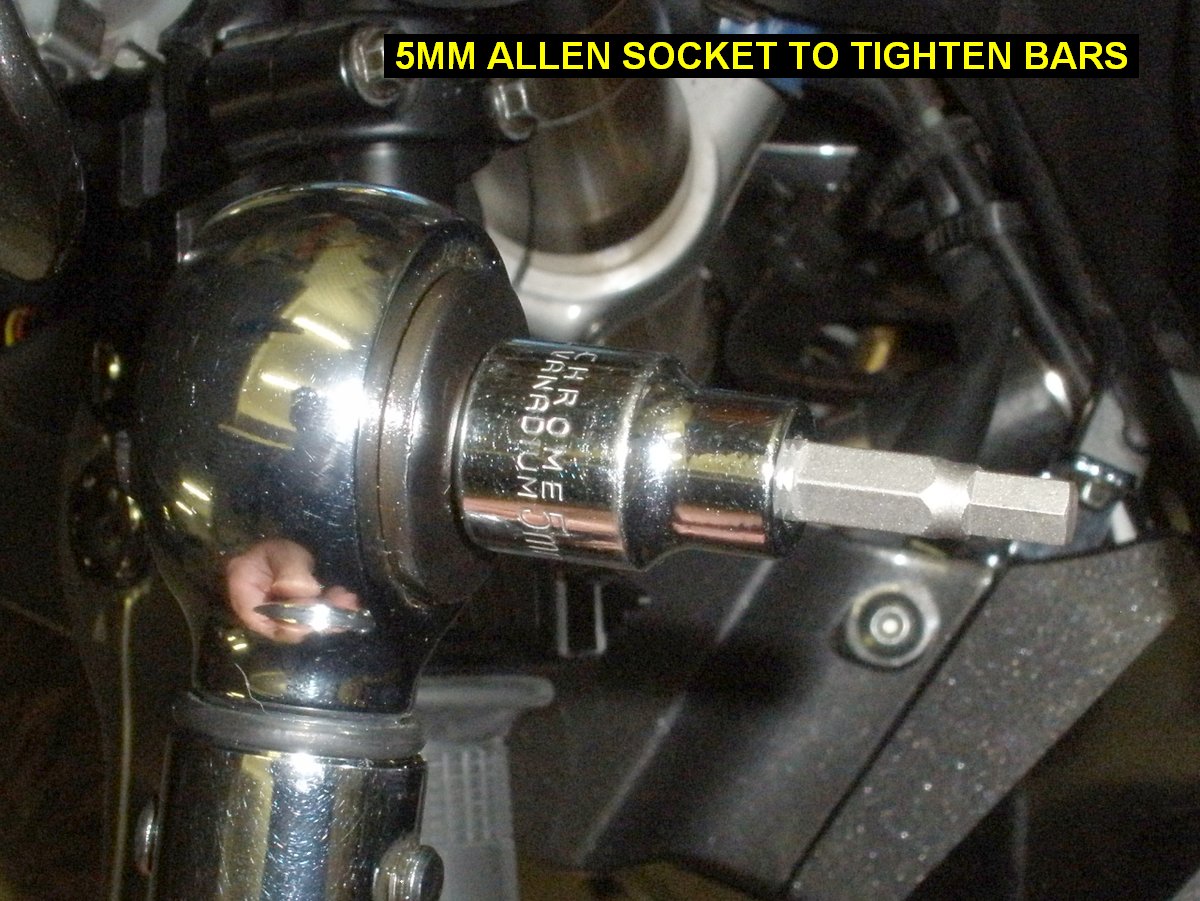
- Sockets: 8mm for brake and clutch controls, 12mm for
stock bars and top triple clamp pinch bolts, 5mm Allen Head for RC-Bars,
41mm
or 1-5/8" socket for the steering stem nut.
- Rubber or plastic hammer to tap on the bottom of the
top triple clamp to remove it.
- Torque Wrenches: (borrow or rent of you have to) a
large torque wrench accurate up to 101 ft�lbs for the
steering stem nut, another mid sized wrench accurate at 25ft�lbs for the fork pinch bolts and
hydraulic banjo bolts, and a small in-lbs torque wrench to put the
handlebar pinch bolts at 96 in-lbs.
- Phillips screw drivers - a shorty one for handlebar switch controls
and a regular sized one for the bar end damper weights.
- Needle nose pliers for removing the inner bar
weights.
- Air compressor with air nozzle - for removing grips
from bars.
- A few towels to protect painted surfaces from scratches
while you work.
- Vise and pliers to bend the front brake reservoir mount
bracket.
Installation Steps:
1) Put the bike up on the rear wheel stand.
2) Remove the windshield, mirrors and fairing stay from the upper fairing to give
yourself more room to work around the handlebars.
3) Put a towel or some sort of protection over the gas
tank just in case you drop the torque wrench or the socket falls off. Turn the
front wheel all the way to the left steering lock and use the 41mm
or 1-5/8" socket to loosen the steering stem
nut.
4) Straighten the front wheel and put the front end up
on the steering stem stand to take weight off the forks.
5) Put towels down on the flat fairing surface below the
clutch and front brake levers to keep the fairing from getting scratched.
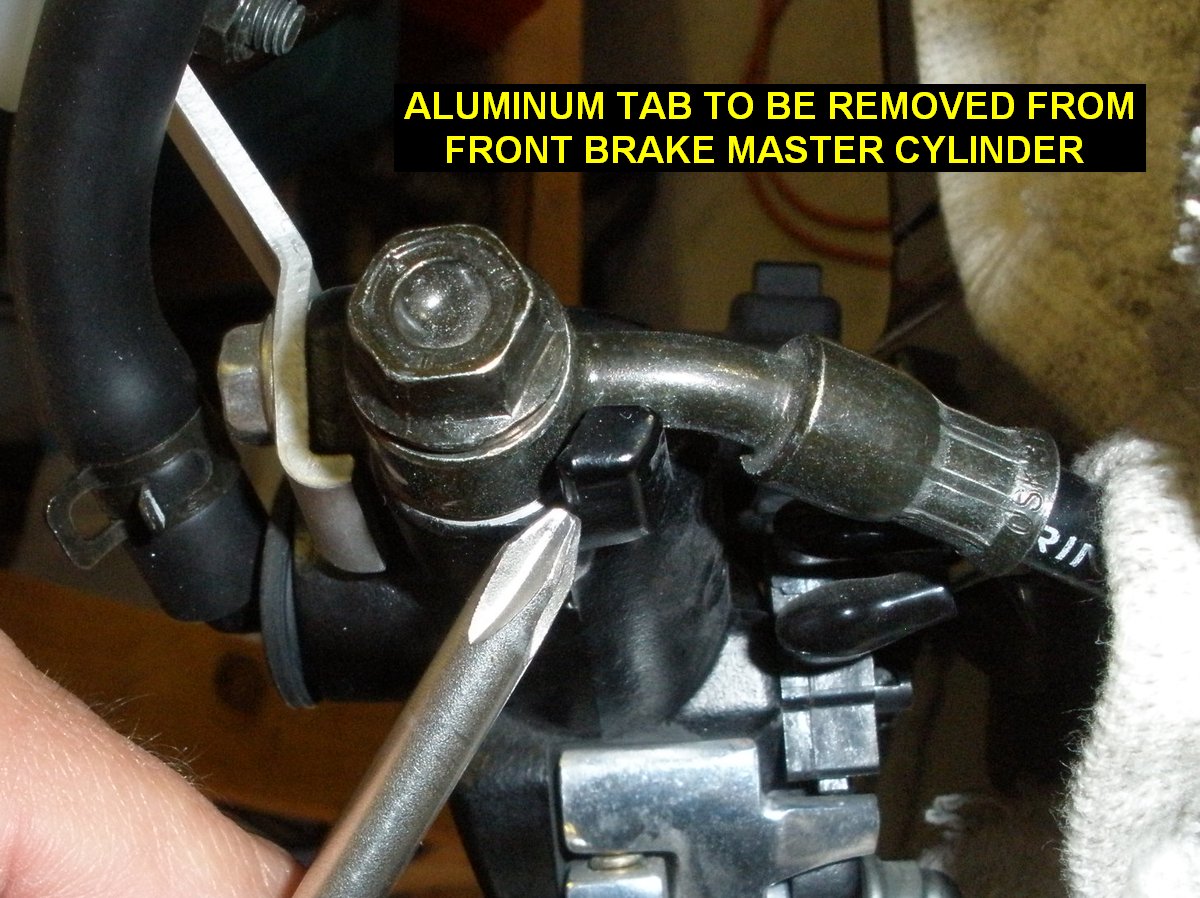
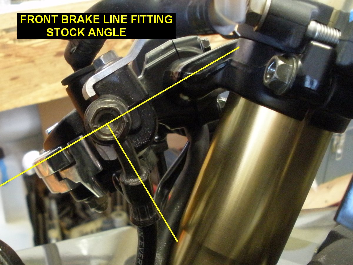
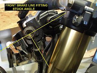
6) Modify the angle of the front brake hose fitting at the master
cylinder. It needs to be more parallel with the fork leg. If done carefully,
it can be done without fluid leaking or having to bleed the brake afterwards.
Follow this procedure:
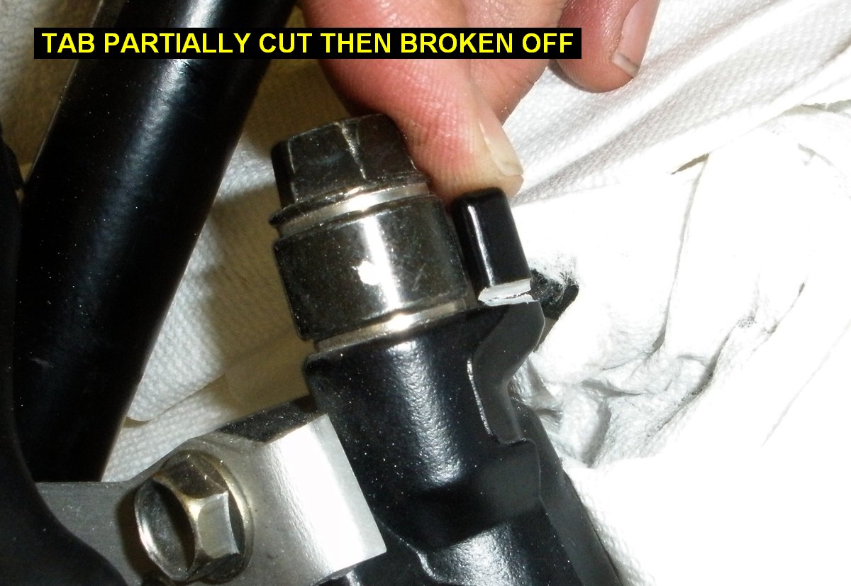
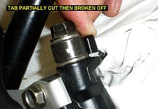
- Use a dremel tool, hacksaw blade or other small saw blade to
cut about halfway into the cast aluminum tab on the master cylinder, then break it off by
prying between it and the banjo fitting. This tab needs to be removed so
you can rotate the brake line further than it currently allows. You may find
it easier to use the steps below to rotate the brake line away from the
tab temporarily to make it easier to cut. Be sure to remove enough of
the tab so the brake line will rotate past it.

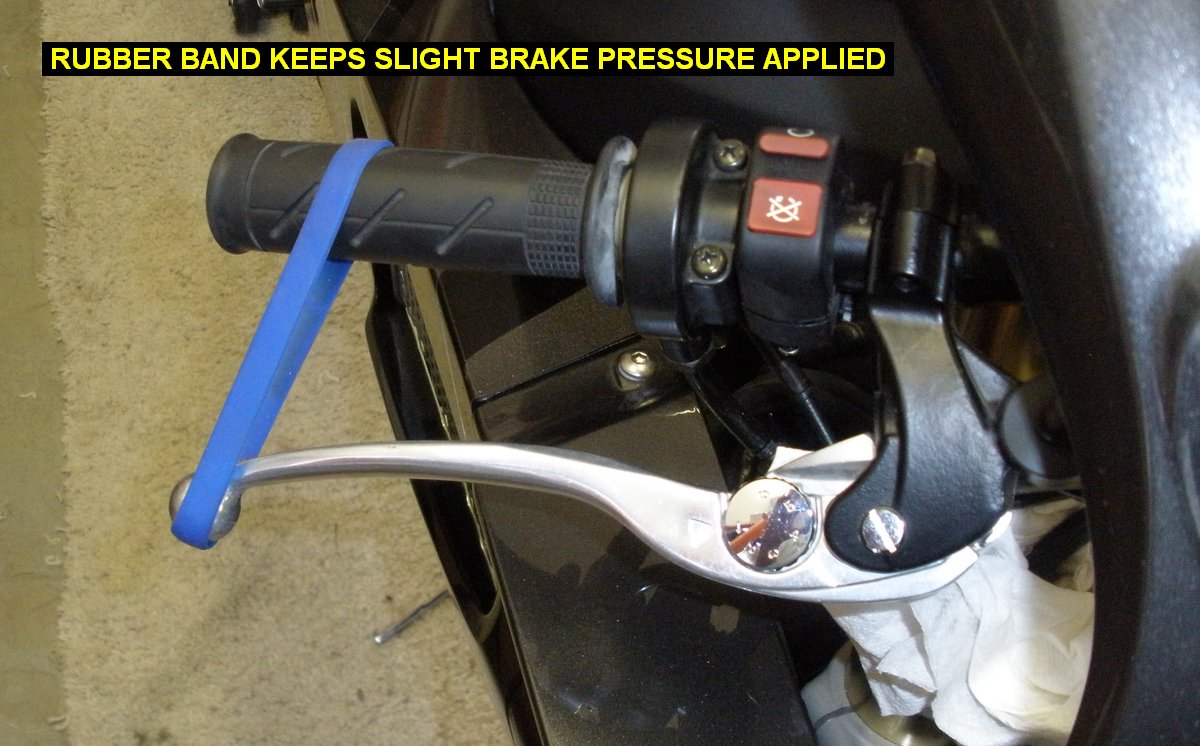
- Put a rubber band on the brake lever to keep slight
brake pressure. This ensures that fluid comes out instead of air going into
the brake line should you mistakenly loosen the banjo fitting too far.
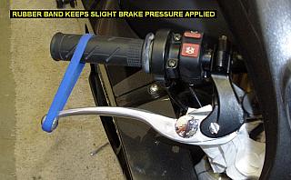
- Put shop towels around the area to protect the painted
surfaces just in case too. Unlike the picture above..dooh!
- Put a 12mm socket on a long breaker bar which gives
you precise control of the banjo bolt. Loosen the banjo bolt a tiny amount
maybe 1/8 to 1/4 of a turn at the most, just enough to allow you to rotate
the brake line fitting with some force by hand. You might find it best
to loosen the banjo a tiny amount then rotate the fitting with the banjo
as you tighten it back up. This tiny movement can be repeated until the
deired angle is acheived.
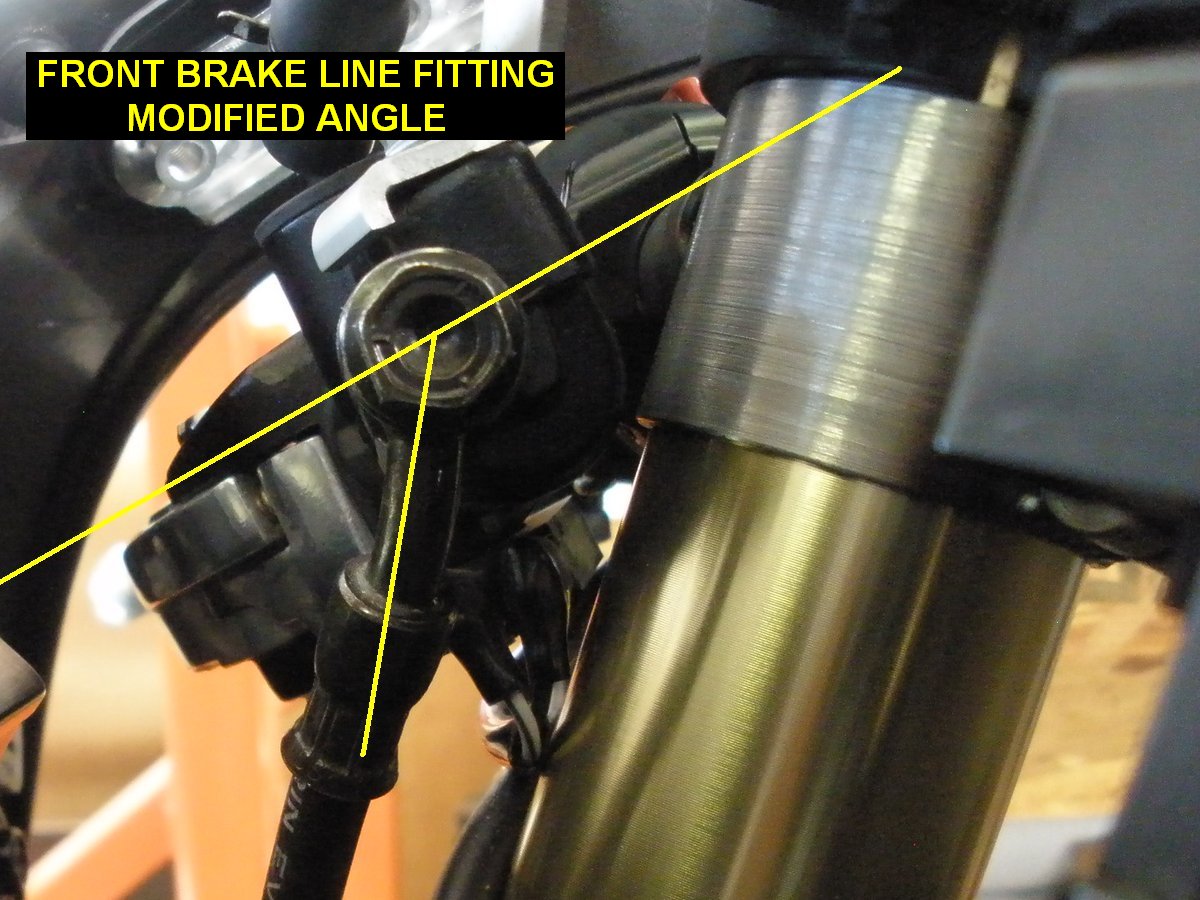
- Rotate the brake line fitting to be more parallel with
the fork leg as shown in the picture. Compare the angles shown in yellow.

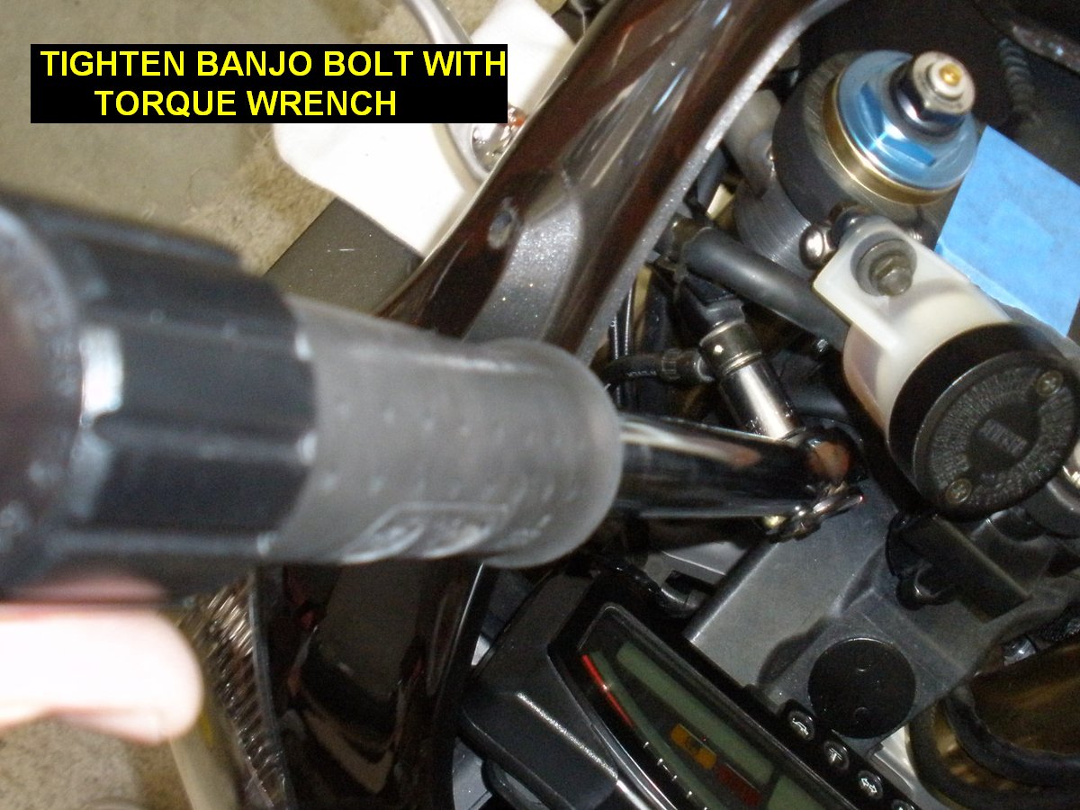
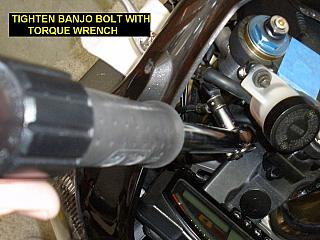
- Hold the fitting in the new position while you re-torque the
banjo bolt to 25ft�lbs. Without the tang there anymore, it will want to
rotate as you tighten the banjo bolt.
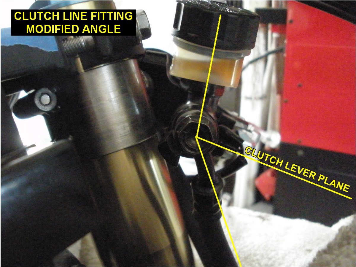
7) Modify the angle of the clutch hose fitting at the master
cylinder. It needs to be more parallel with the fork leg too. Again, If done carefully,
it can be done without fluid leaking or having to bleed the clutch afterwards.
Follow the same procedure as you did for the brake fitting except do not
remove the tang. We're rotating the fitting the other direction away from the
tang so it's not in the way.
- Adjust the clutch fitting to this angle:
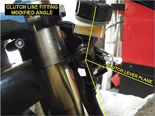
- As before, hold the fitting in the new position while you re-torque the
banjo bolt to 25ft�lbs.
8) Prepare the left handlebar for removal:
- Loosen and remove the clutch lever/master cylinder
assembly and turn-signal/hi-beam switch module. Since you've protected
your fairings, they can just rest on the fairing until reinstallation.
- Use a phillips screw driver to remove
left bar
end damper weight.
- Remove the left grip, using the air nozzle just under
the rubber to pressurize it. You may have to use your hand to block off air
escape so it pumps up enough to slide off the bar.
9) Prepare the right handlebar for removal:
- Loosen and remove the front brake lever/master
cylinder assembly and kill switch module. Since you've protected your
fairings, they can just rest on the fairing until reinstallation.
- Use a phillips screw driver to remove the right bar
end damper weight.
- Remove the screws and remove the top cap from the throttle housing.
- Due to throttle cable length, you cannot remove the
throttle housing/tube assembly at this time, it will come of in a later
step. There's no need to remove the throttle grip either.
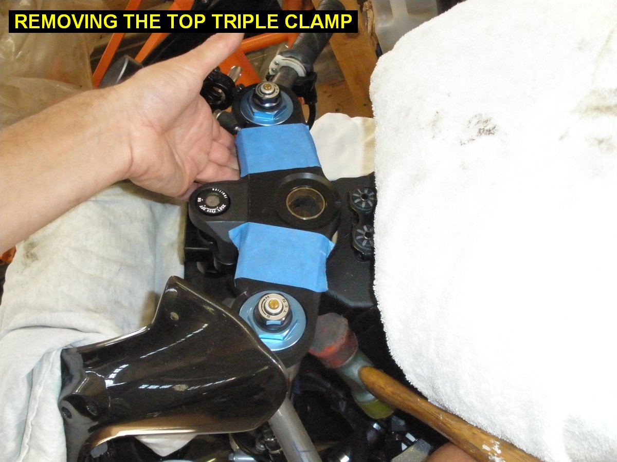
10) Put a towel over the instrument panel to protect it.
Same thing for the gas tank. Loosen the fork pinch bolts on the top triple
clamp, and remove the steering stem nut. Put some upward pressure by hand on
one side of the top triple clamp then use a rubber or plastic hammer to gently
tap upward from below on the other side to remove it. Let the triple clamp
rotate forward and rest on the towel on the instrument panel. The ignition
lock will keep you from taking it totally off the bike.
Do not use a rear wheel stand as the only method of
holding the bike while removing the steering stem, it puts excessive load on
the forks and bottom triple clamp. As mentioned before, use of a steering stem
stand or anything similar is best. Don't put blocks under the oil filter
either!

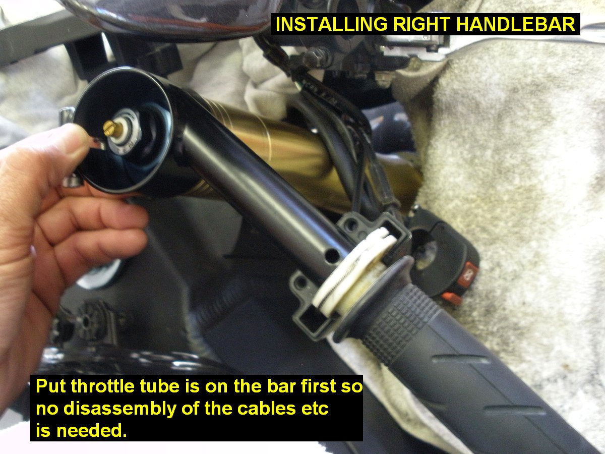
11) Loosen the clamp bolts and remove the left and right
handlebars. To remove the right bar, you'll have to slide the throttle inwards towards
the fork to find a spot that allows you to remove the bar off the fork leg, then
slide the throttle assembly off the bar. Remove the circlips off both fork legs
too, they are not used with the new RC-Bars.
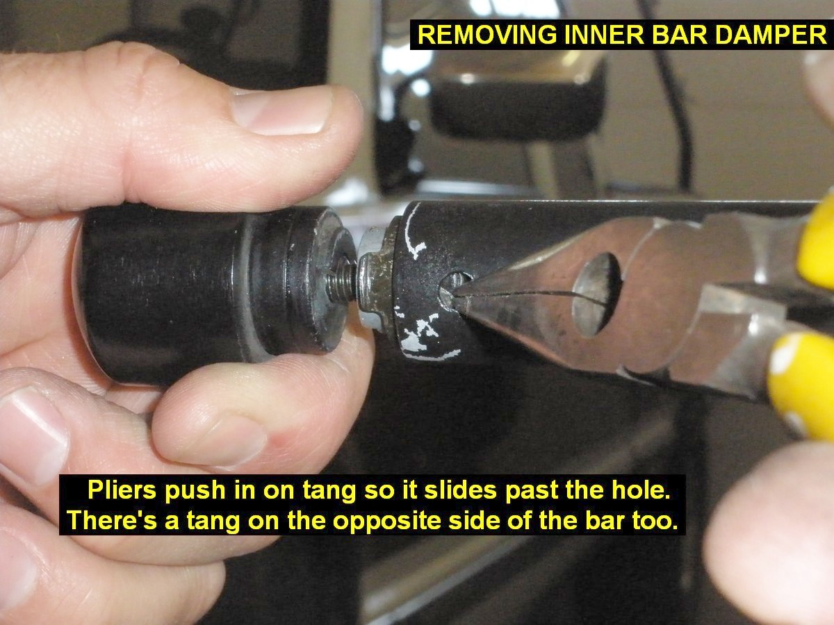
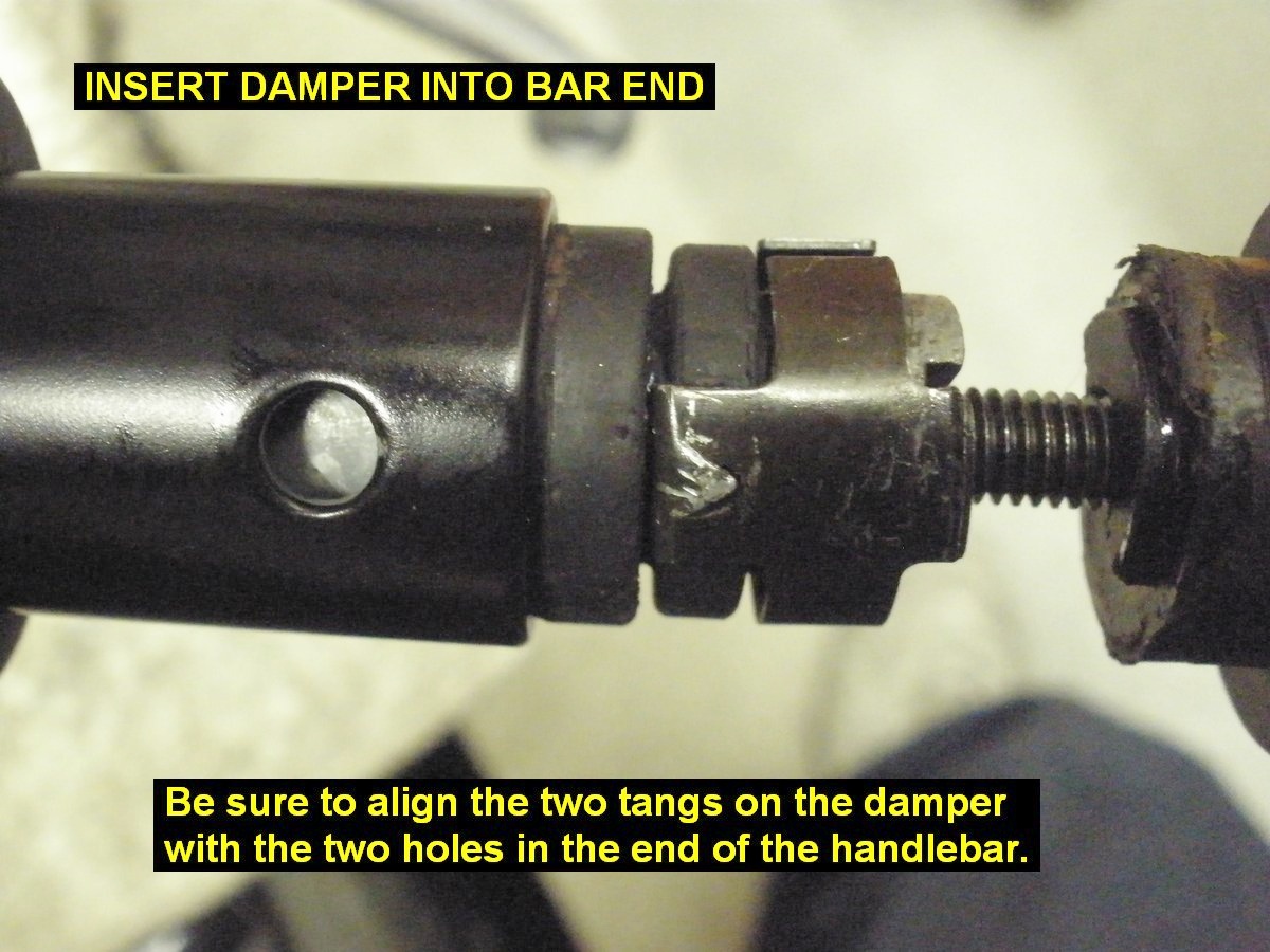
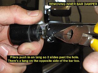
12) Remove the internal dampers from
the bars. Put each handle bar into a vise to hold it securely. Screw the bar
weight end back on to use as a handle to pull the inner weight out. Use needle
nosed pliers to push in the tangs in the holes at the end of the bar and you
apply pulling pressure on the end weight. This allows the inner weight to slide
out the of the bar. Expect to have to pull pretty hard, wiggle it around etc,
because the rubber part of the damper is probably stuck to the inner bar, plus
the tangs don't like to slide out of the tube either.
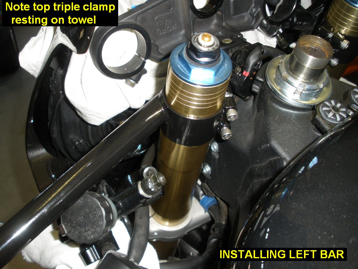
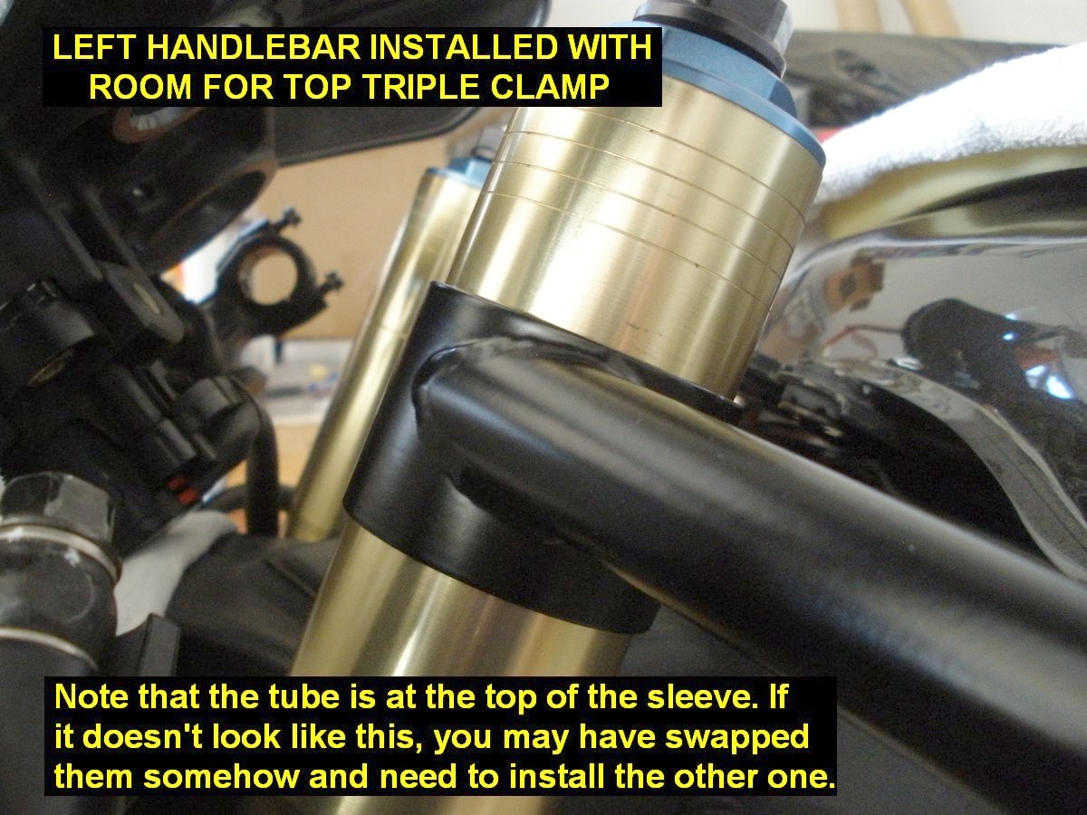
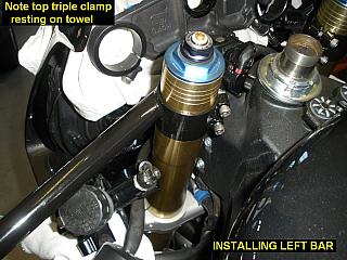
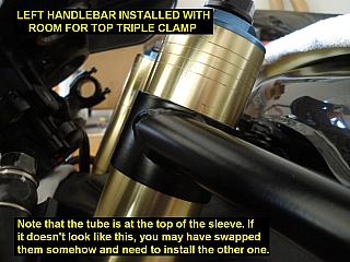
13) Install the left RC-Bar onto the fork leg and slide it
down far enough to get the trip clamp back on. Note that when installed
correctly, the handlebar tube will be
at the top of the sleeve that slides over the fork leg. If not, you have the
wrong one on and need to swap it.
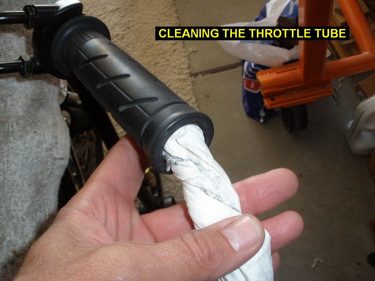
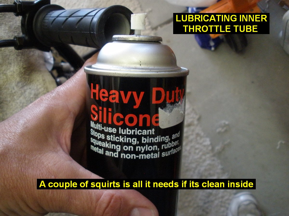
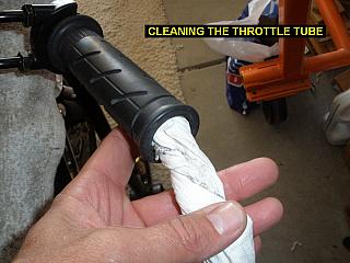
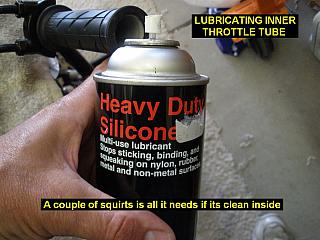
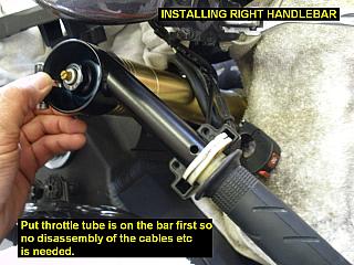
Before installing the right
bar, clean out the throttle tube if needed and put the throttle tube/cable assembly on first, then slide it up the bar as needed to allow you to
slip the sleeve onto the fork leg.
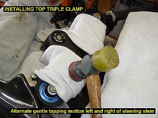
14) Reinstall the top triple clamp:
- Put cloth protection down on the top triple clamp
then gently tap it down evenly onto the fork legs and stem until it
bottoms. Tap it down alternating one light tap left of the steering
stem-one light tap right side of steering stem....
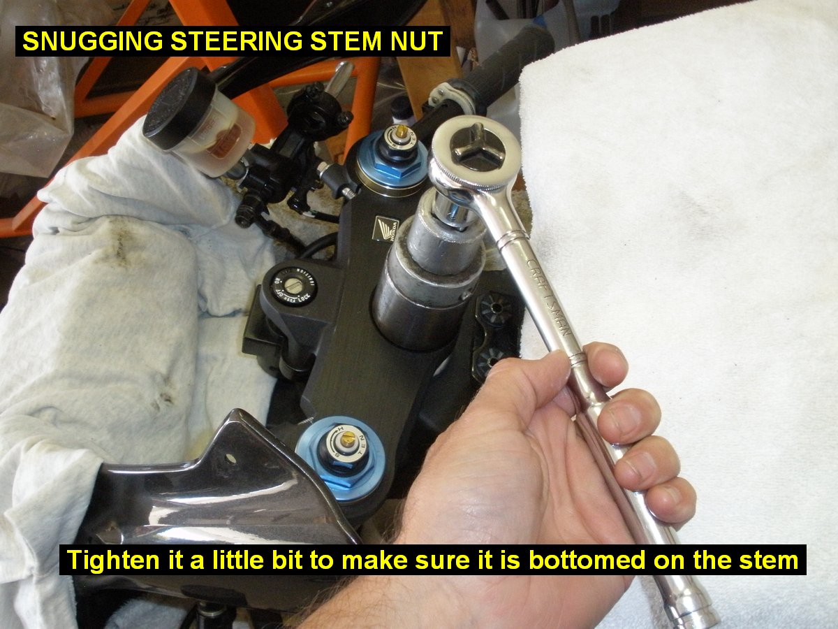
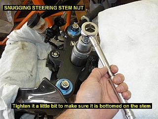
- Install the stem nut and tighten it a little bit to
make sure it is in truly bottomed on the stem.
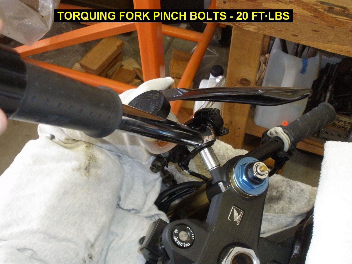
- Torque the two fork pinch bolts to 20 ft�lbs.

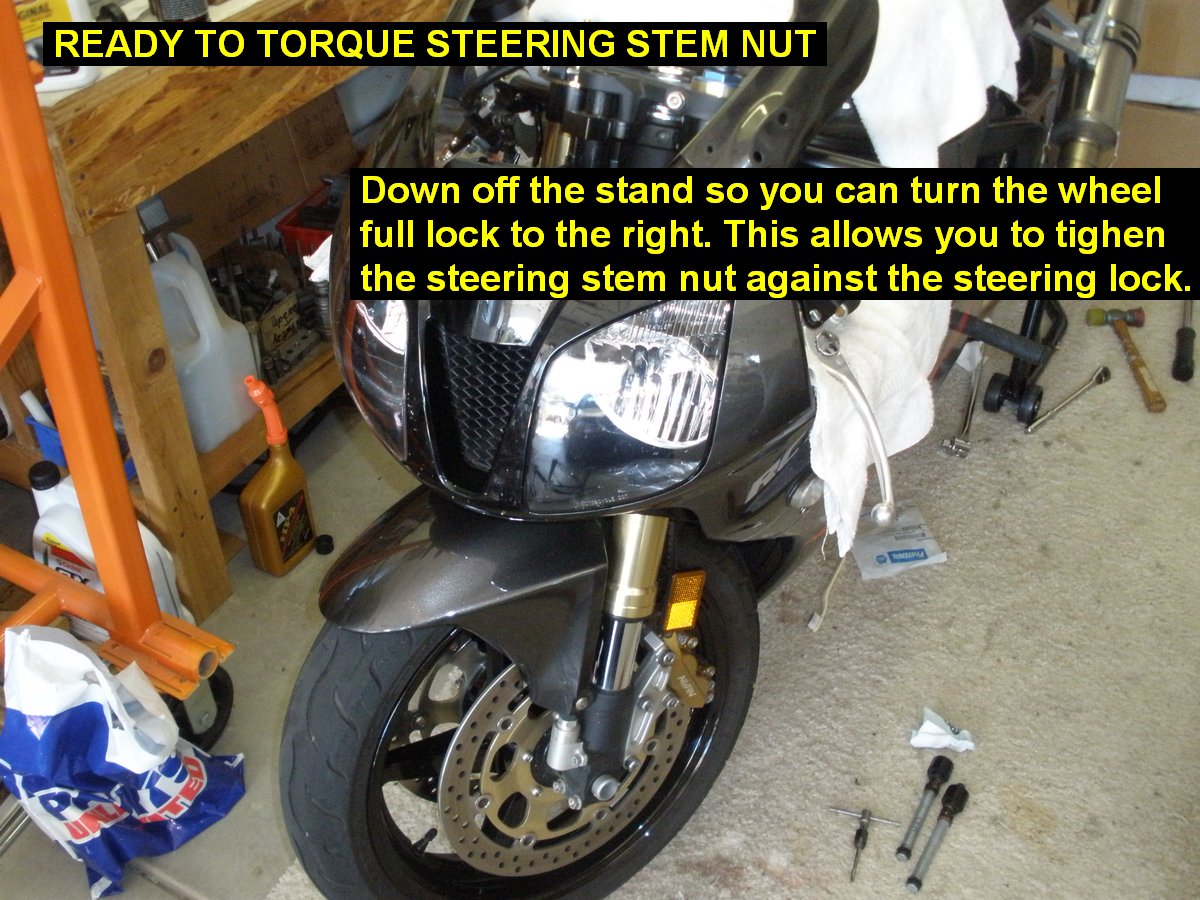
- Take the front end, down off the stand and rotate
the front wheel to full right steering lock.
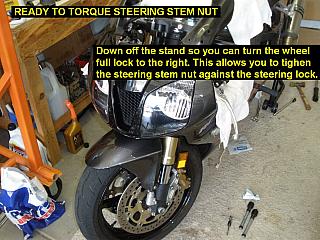
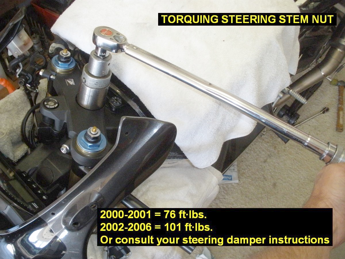
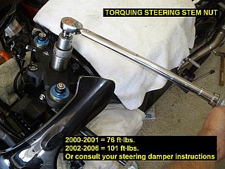
- Torque the steering nut to the appropriate torque
value for your year of RC51:
2000 & 2001 = 76 ft�lbs, 2002 to 2006 = 101ft�lbs
- Note: Scotts Steering Damper nut shown in
pictures. Scotts says to torque their steering stem nut to factory
setting up to 85 Ft�Lbs, so 2002-2006 is set to that limit when using
their nut.
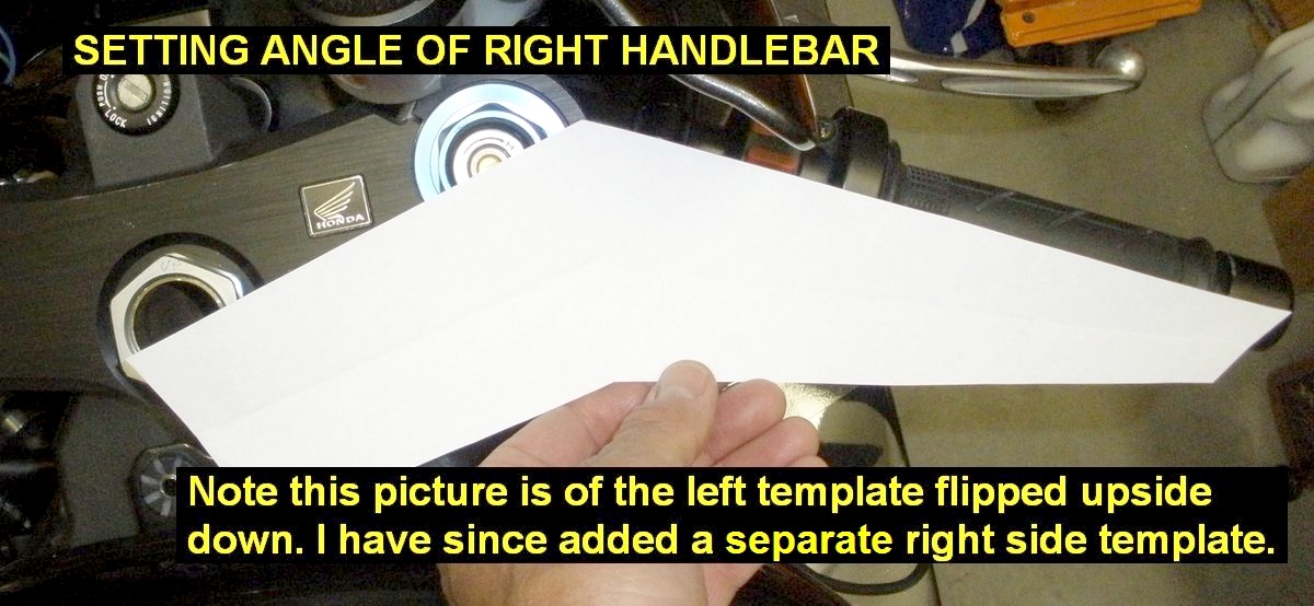
15) Position and snug the RC-Bars:
- Download, print and cut out the RC-Bars Adjustment
Sight Gage templates:
LEFT TEMPLATE RIGHT
TEMPLATE.
The templates are used to set the angle between the bar, fork tube and steering
stem. It may help to glue or tape it to something rigid like cardboard.
- Slide each handlebar up until it touches the bottom
of the triple clamp, set it roughly at the correct angle and snug up the
pinch bolts equally and a little each at a time so that the bar can
still be adjusted if pushed with some force.
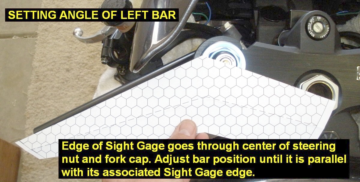
- Adjust the angle of each bar as shown in the
pictures. Do not wear glasses that distort angles as you move your head
viewing angle. Just use your eyeballs alone. Try to hold the template on
a parallel plane to the top of the triple clamp, then sight down the
center of the fork cap, steering stem and the handle bar.
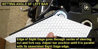
- Adjust the bar so it is parallel with the edge of
the template when the other edge of the template is held directly over
the center of the fork cap and center of the steering stem.
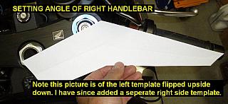
- Use the other template to do the throttle side.
Obviously the throttle tube will make this job a little more difficult,
but with practice and measuring many times back and forth left/right you
can get the bars set at the proper and equal angles.
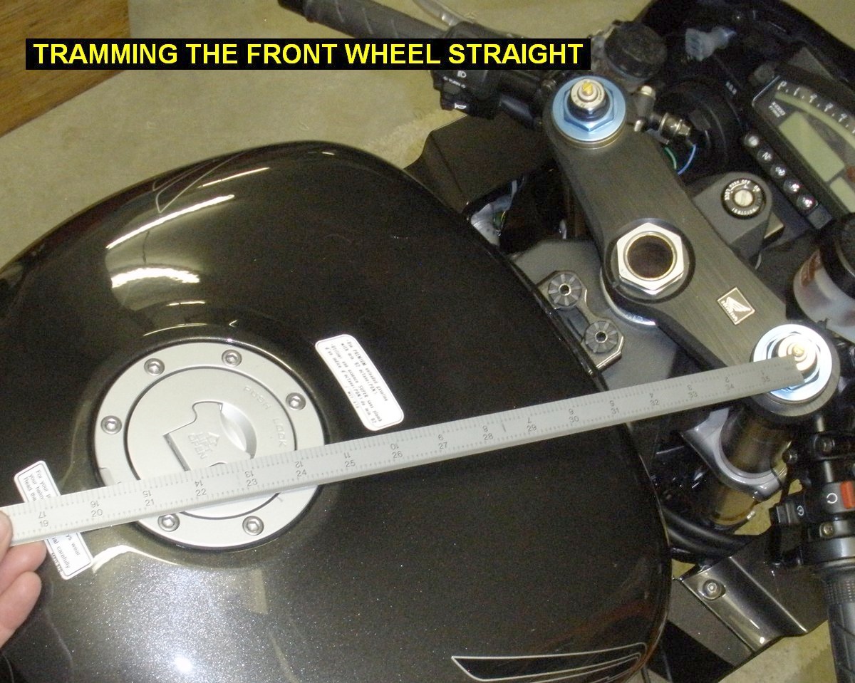
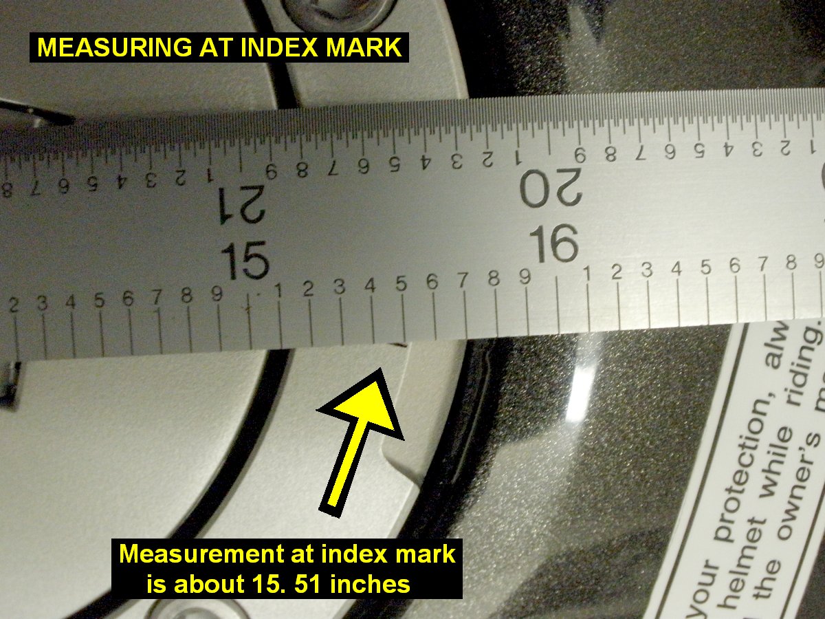
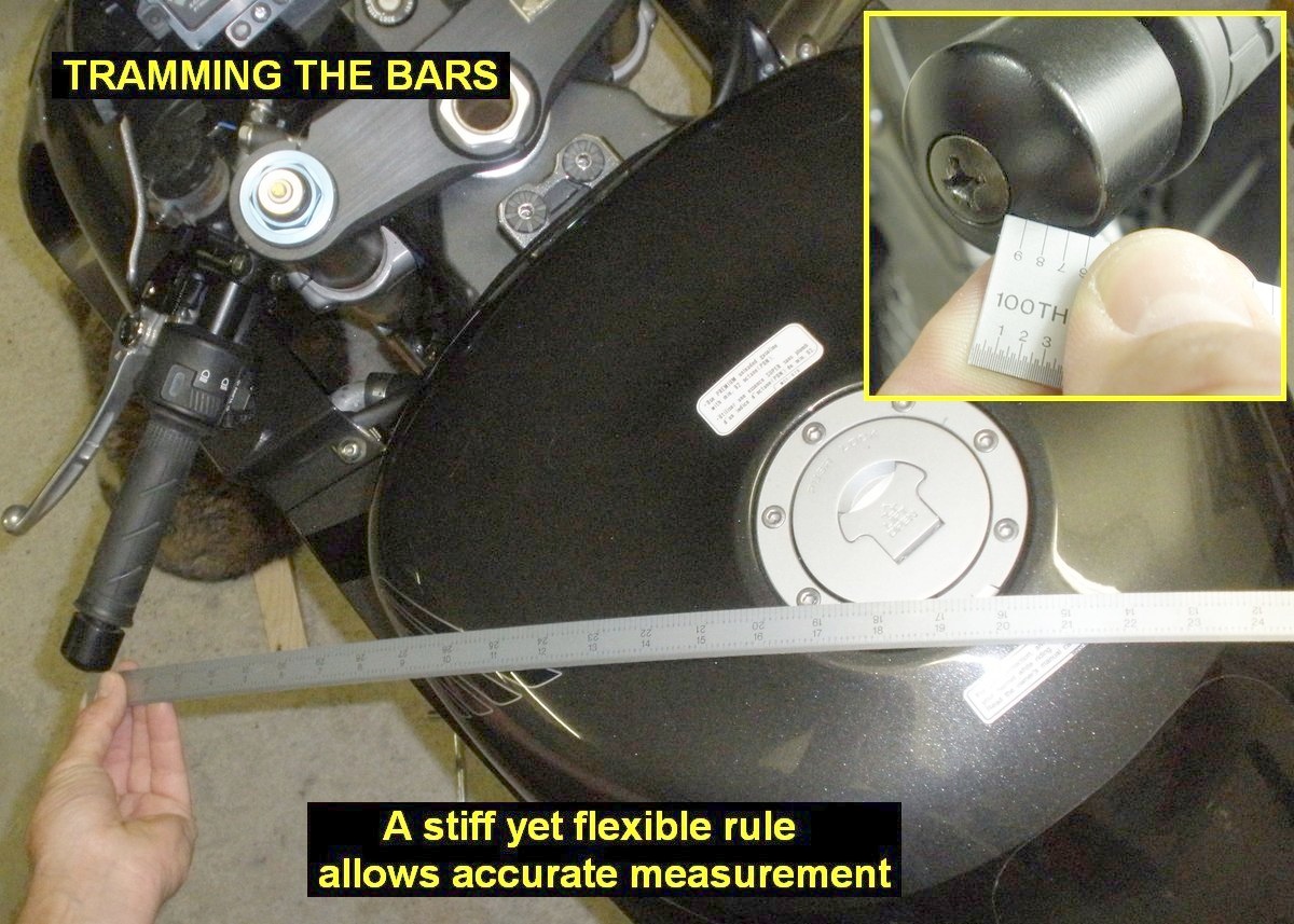
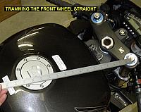
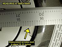
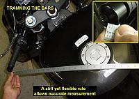
| Optionally - you can tram the bars using a
flexible steel rule or something similar. First put a tiny mark on the
center aft of the gas cap ring with a sharpie pen. Tram the front wheel
to a position of exact straightness by measuring the distance from each
fork cap to the index mark. Adjust the wheel position until you get the
measurements exactly equal. Pick a reference mark on the ends of the
bars, for example the closest edge of the screw in the middle of the
damper weight, and compare measurements to the index mark. Assuming the
measurements are not equal, adjust one of the bars a little. Assume you
knocked the wheel out of center doing this, and re-tram the front wheel
straight again before re-measuring the bars. Repeat as needed until you
get them equal to your satisfaction.
When I did this I found that using
the templates I had placed the bars within 0.05 inch of each other,
certainly well within reasonable tolerance.
|
- When you are happy with their position, snug the
pinch bolts equally and a little each at a time, enough so the bars will
not move when steering from lock to lock. We will torque them to the
final setting later, when we verify that everything fits, works together
and steers from lock to lock without interference.
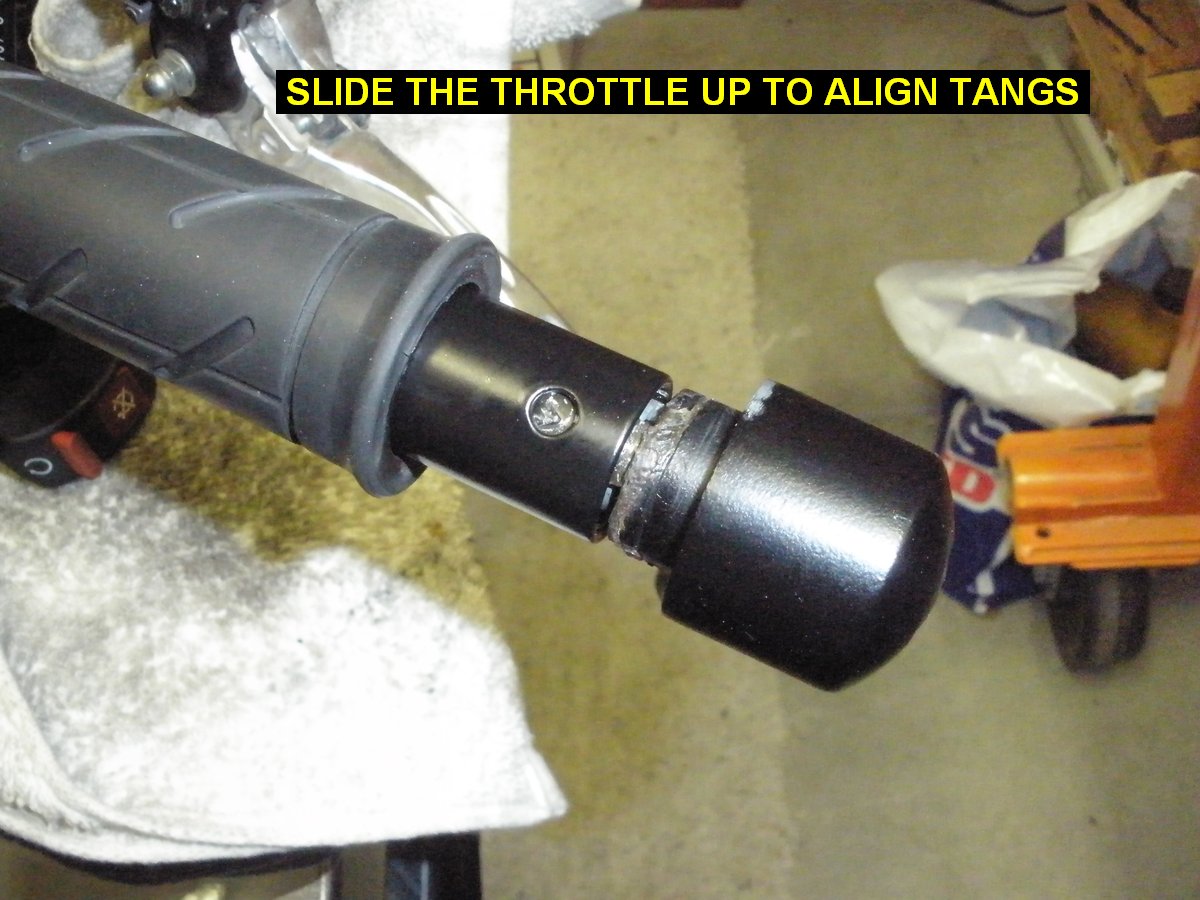
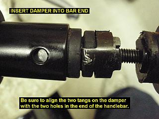
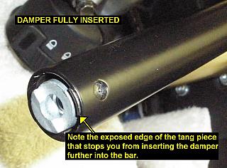
16) Install the dampers into the bars - Screw the weights on
to the dampers, they don't have to be tight. Align the tangs of the with the two
holes in the end of the bars. Push them in until they are stopped at the end of
the bar by the raised edge of the tang piece. You'll have to slide the
throttle up the bar a little to see the holes in the end, but afterwards you can
tighten the weight. Take off the weight on the left side after installing the
damper, because you still need to put the grip back on.

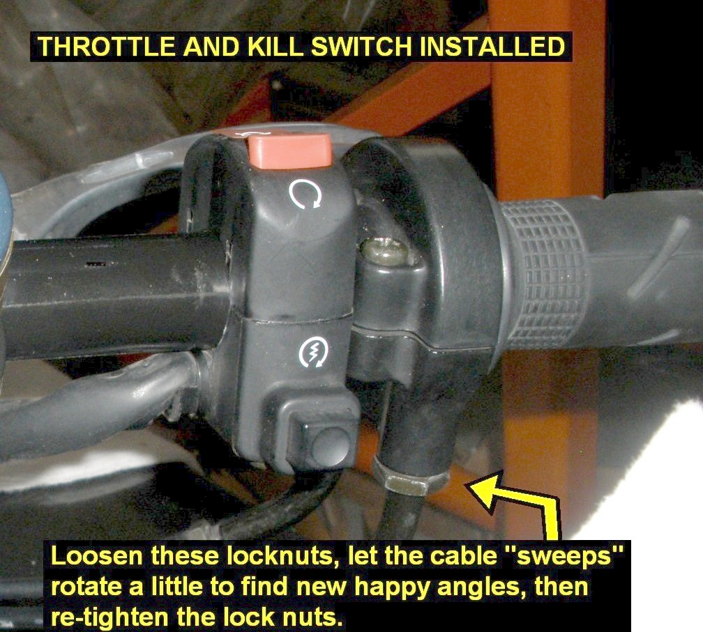
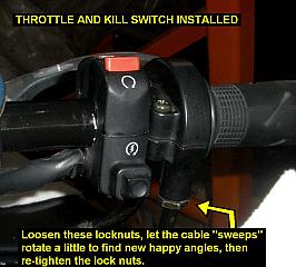
17) Install the the throttle housing, aligning the pin into the hole in the bar. Both screws are equal length. Tighten them up.
Install the kill switch aligning the pin in the bottom half into the hole in the
bar. The longer screw goes in the aft hole. Tighten it up. Depending on your
screwdriver collection you might find it easier to install the kill switch first
that way you can push the throttle cables out of the way so you can tighten that
front kill switch screw. Since the throttle is in a different location than it
used to be, loosen the two locknuts and readjust the the two throttle cable
"sweeps" that
enter the throttle housing. The angles won't change much, but they will each
find a new neutral "happy" position, then tighten the lock nuts again.
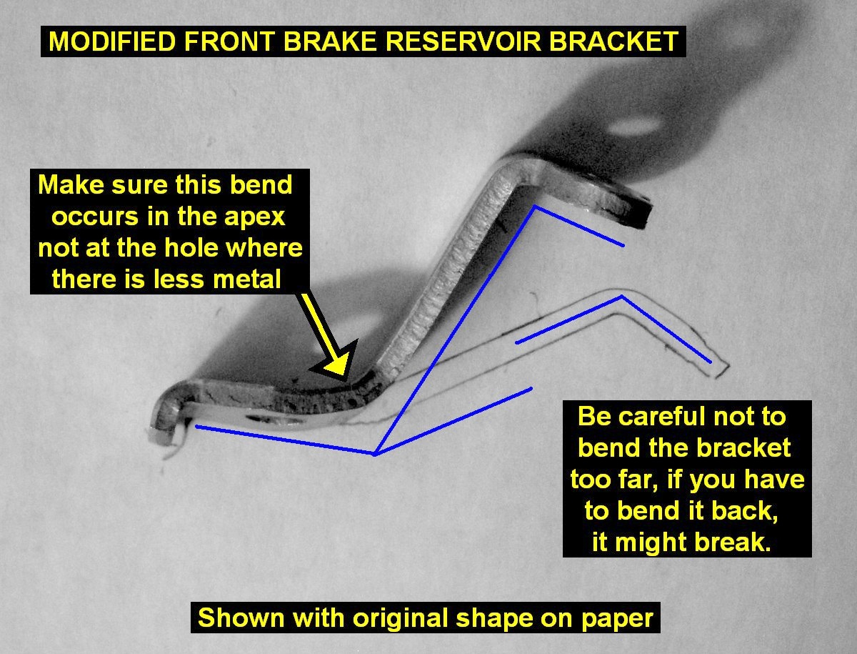
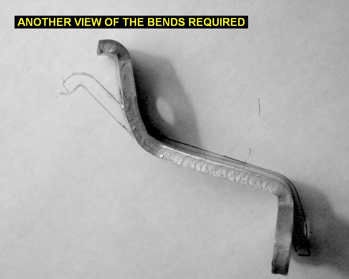
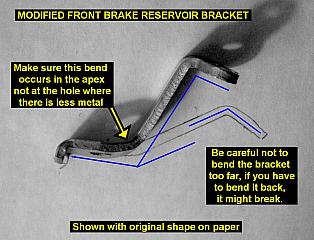
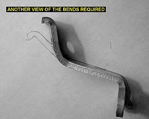
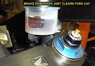
18) Remove the little aluminum bracket holding the front
brake master reservoir. CAREFULLY bend it as shown in the picture. Print out the
picture and set the bracket on the picture as you go along to help you get the
angles right. Try not to bend it too far, because it may break if you try to
bend it back and forth too much.
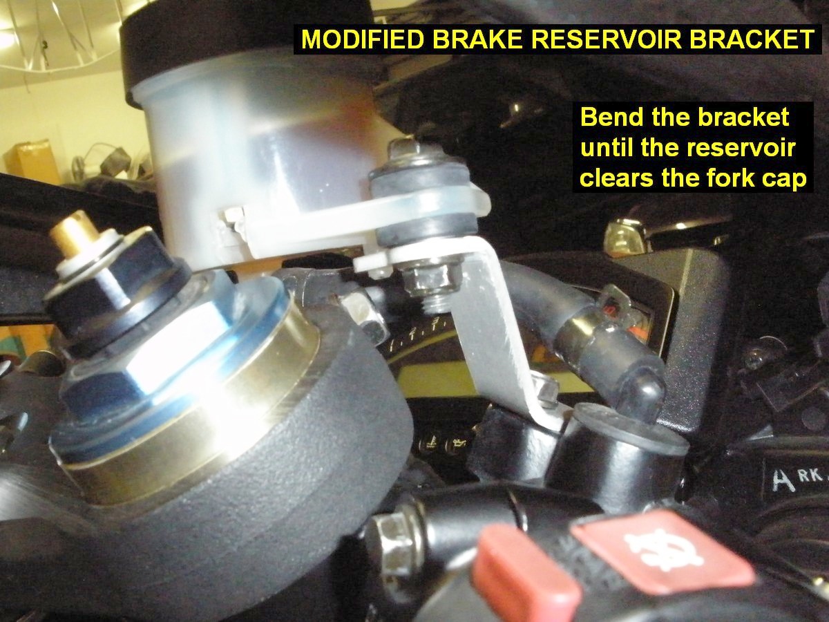
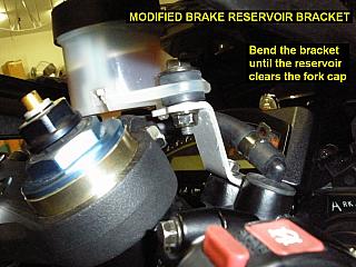
19) Install the modified bracket on the master cylinder, then
install the front brake lever assembly on the bar in your favorite location, but
don't tighten it up all the way yet. You may decide to move it once you get the
clutch lever in position and start testing steering lock. Keep in mind that some
locations may require a little more bending/modification to the reservoir bracket.
Caution: To avoid scratching the finish, loosen the brake/clutch controls adequately before rotating or sliding them on the bars!
20) Install the left grip and bar end weight. Overhang the
grip so it looks similar to the throttle side, with the same amount of bar
weight sticking out.
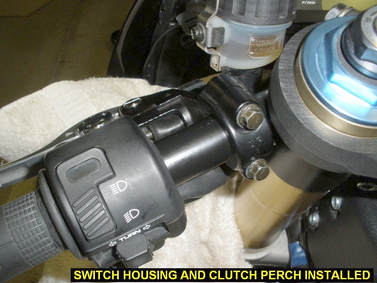
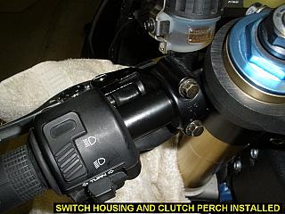
21) Install the Hi/Lo Beam/Turn Signal housing, aligning
its pin into the hole in the bar. The screws are equal length.
22) Install the clutch perch/lever assembly. Because of
differences in design from the front brake perch, the clutch bar clamp will most likely end up as
close to the fork tube as you can put it.
23) Sit on the bike and adjust the position of the brake and
clutch controls, then tighten them up.
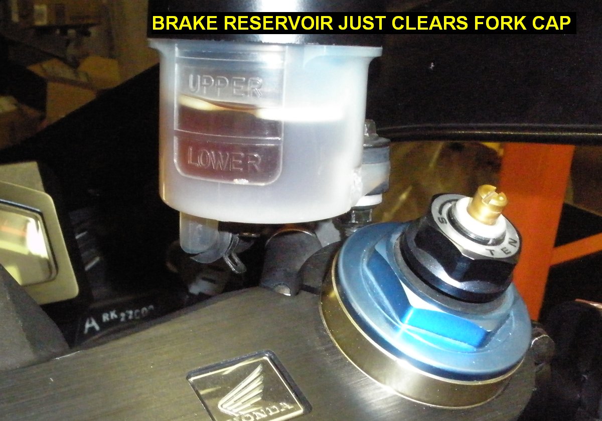
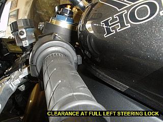
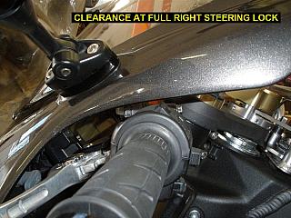
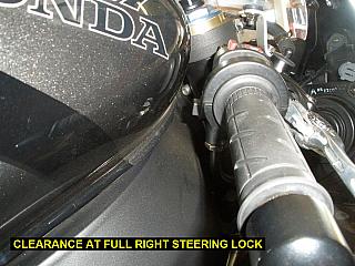
24) Remove all the towels etc so you can observe the
moving cables and hoses as you steer left to right and right to left, full
lock. If you've got the bars where they should be and all the adjustments
talked about above done, you should not have any cable or hose problems, and
nothing hits the fairing or gas tank although they get close. Use the template again and verify that the bars are
equal angles. Sit on the bike and see if the bars look and feel to be at the
same angle. See pictures below
for clearances at full lock:
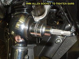
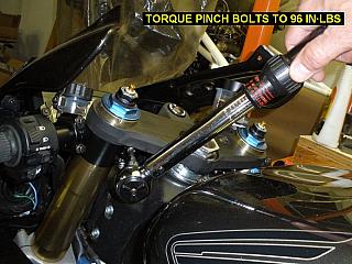
25) Tighten the bars to 96 in-lbs: Use the small torque wrench
with a 5mm allen wrench socket as follows:
- Using Loc-Tite is not recommended because a tiny
amount of anti-sieze has been applied to the pinch bolt threads to
prevent galling of the stainless steel bolts.
- Start out by torquing them both to 90
in-lbs then finish at 96in-lbs.
- Torque them equally in alternating increments so
the load placed upon them stays somewhat equal as they both get tighter.
- Apply smooth slow pressure to the wrench to ensure
accurate indication of the wrench.
- Since one bolt tightening will release tension on
the other bolt, check final torque on each bolt in alternating
increments over and over - until both bolts stop moving and will not
tighten further without exceeding 96 in-lbs
set into the wrench.
- Over-tightening hardware is just as bad as
under-tightening.
- Use of Torque-Seal or tiny dabs of paint on the
pinch bolts is a good way to visually see they have not loosened over
time. Otherwise you should periodically check them with the torque
wrench.
26) Install your fairing stay, windshield and mirrors then take it out for a test ride!
Have fun and ride safe!